- 您现在的位置:买卖IC网 > Sheet目录288 > 2866666 (Phoenix Contact)RECHARGEABLE BATT MODULE 24VDC
MINI-DC-UPS/24DC/2
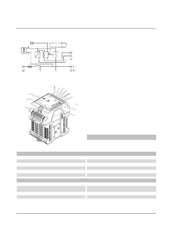
Block diagram
t...[min]
Battery
L(+)
N(-)
Structure
PS
R1
R2
Remote
On/Off
Alarm
Bat. Mode
Charge
+24 V/2A
1
AC input
"
7
1
2 4
5
6
8
3
9
0
2
3
4
5
6
7
8
9
DC output
Rechargeable battery connection
Active relay output: Alarm
Active relay output: Battery mode
Active relay output: Battery charge
Potentiometer 22.5 V DC ... 29.5 V DC
Remote shutdown (R1, R2)
Red control lamp: Alarm
!
10
11
12
Yellow control lamp: Battery mode/ Battery charge
Green control lamp: Power In OK / Overload
Buffer time setting 0.5 min ... 30 min and continuous
[mm 2 ]
AWG
[Nm]
solid
stranded
Torque
Input
Output
Signal
0.2 - 2.5 0.2 - 2.5
0.2 - 2.5 0.2 - 2.5
0.2 - 2.5 0.2 - 2.5
24 - 12
24 - 12
14 - 24
0.5 - 0.6
0.5 - 0.6
0.5 - 0.6
Input data
Input nominal voltage range
AC input voltage range
DC input voltage range
Input fuse, integrated
Type of connection
Stripping length
Output data
Nominal output voltage
Setting range of the output voltage
Output current
Type of connection
Stripping length
100 V AC ... 240 V AC
85 V AC ... 264 V AC
100 V DC ... 350 V DC
3.15 A (slow-blow, internal)
COMBICON screw/plug connection
8 mm
24 V DC
22.5 V DC ... 29.5 V DC (normal mode; in the buffer mode, dependent on a
battery voltage of 27.9 V DC ... 19.2 V DC)
2A
COMBICON screw/plug connection
8 mm
103123_00_en
PHOENIX CONTACT
5
发布紧急采购,3分钟左右您将得到回复。
相关PDF资料
29SM-K711-99V
MOTOR STEP UNI 71MM 24V DL SHFT
2IOM24
I/O MOUNTING BOARD MINI 24POS
3-102935-6
40 LEVEL V ASSY DR .125CL
3-106176-1
CONN MOD JACK 4/4POS SMT VERT
3-1375192-1
CONN MOD JACK 6/6POS PCB VERT
3-1393531-3
V23535A3280C261=BKMOD422 FEDER
3-1589455-7
CONN PLUG 25POS 30AWG 6IN
3-1589476-6
CONN RCPT 65POS 30AWG 6IN
相关代理商/技术参数
2866679
功能描述:DIN导轨式电源 QUINT-PS/1AC/48DC/5A 48VDC 5A
RoHS:否 制造商:Mean Well 产品:Linear Supplies 商用/医用:Commercial 输出功率额定值:960 W 输入电压:180 VAC to 264 VAC, 254 VDC to 370 VDC 输出端数量:1 输出电压(通道 1):48 V 输出电流(通道 1): 输出电压(通道 2): 输出电流(通道 2): 输出电压(通道 3): 输出电流(通道 3): 尺寸:150 mm L x 110 mm W
2866682
功能描述:DIN导轨式电源 QUINT SFB 1PHASE 48V DC 10A
RoHS:否 制造商:Mean Well 产品:Linear Supplies 商用/医用:Commercial 输出功率额定值:960 W 输入电压:180 VAC to 264 VAC, 254 VDC to 370 VDC 输出端数量:1 输出电压(通道 1):48 V 输出电流(通道 1): 输出电压(通道 2): 输出电流(通道 2): 输出电压(通道 3): 输出电流(通道 3): 尺寸:150 mm L x 110 mm W
2866695
功能描述:DIN导轨式电源 QUINT-PS/ 1AC/48DC/20 RoHS:否 制造商:Mean Well 产品:Linear Supplies 商用/医用:Commercial 输出功率额定值:960 W 输入电压:180 VAC to 264 VAC, 254 VDC to 370 VDC 输出端数量:1 输出电压(通道 1):48 V 输出电流(通道 1): 输出电压(通道 2): 输出电流(通道 2): 输出电压(通道 3): 输出电流(通道 3): 尺寸:150 mm L x 110 mm W
2866705
功能描述:DIN导轨式电源 QUINT SFB 3PHASE 24VOLT 10AMP
RoHS:否 制造商:Mean Well 产品:Linear Supplies 商用/医用:Commercial 输出功率额定值:960 W 输入电压:180 VAC to 264 VAC, 254 VDC to 370 VDC 输出端数量:1 输出电压(通道 1):48 V 输出电流(通道 1): 输出电压(通道 2): 输出电流(通道 2): 输出电压(通道 3): 输出电流(通道 3): 尺寸:150 mm L x 110 mm W
2866718
功能描述:DIN导轨式电源 QUINTPS/1AC/12DC/15A 12VDC 15A
RoHS:否 制造商:Mean Well 产品:Linear Supplies 商用/医用:Commercial 输出功率额定值:960 W 输入电压:180 VAC to 264 VAC, 254 VDC to 370 VDC 输出端数量:1 输出电压(通道 1):48 V 输出电流(通道 1): 输出电压(通道 2): 输出电流(通道 2): 输出电压(通道 3): 输出电流(通道 3): 尺寸:150 mm L x 110 mm W
2866721
功能描述:DIN导轨式电源 QUINT-PS/1AC/12DC/20 12VDC 20A
RoHS:否 制造商:Mean Well 产品:Linear Supplies 商用/医用:Commercial 输出功率额定值:960 W 输入电压:180 VAC to 264 VAC, 254 VDC to 370 VDC 输出端数量:1 输出电压(通道 1):48 V 输出电流(通道 1): 输出电压(通道 2): 输出电流(通道 2): 输出电压(通道 3): 输出电流(通道 3): 尺寸:150 mm L x 110 mm W
2-86672-4
制造商:TE CONNECTIVITY 功能描述:N CONN HSG 10POS W/EARS
2-86673-0
功能描述:FFC & FPC连接器 026 HOUSING FFC RCPT 100CL DR RoHS:否 制造商:JAE Electronics 产品类型:Plugs 系列:HD 节距:0.5 mm 位置/触点数量:40 安装角: 安装风格:Cable 外壳材料:Plastic 触点材料:Copper Alloy 触点电镀:Gold 电压额定值:100 V per contact 电流额定值:0.24 A to 1 A
